Feeling a little nostalgic today, I dug up an picture of a project that I undertook during my undergrad years.
If I recall correctly, this was made while I was in an Experimental Multimedia unit in 2000 and we were learning how to hook up physical sensors to a computer (using an EZIO board and Macromedia Director). However this wasn’t my final project, it was something that I used to explore and experiment.
Anyway, I initially butchered a Nintendo Powerglove off Ebay (it was cheap because the seller had a typo in the name and no one else bid for it) for its flex sensors. This worked, but if I recall correctly the resistance response wasn’t linear but the EZIO ADC, so this meant that I lost resolution and couldn’t reliably tell the difference between a lightly closed hand and a fist.
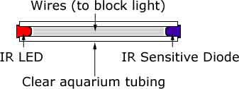
In the end, I made my own flex sensors. Unfortunately, it was so long ago that I can’t remember the journey that lead me to this design. In a nutshell, each flex sensor was an IR LED, an IR sensitive diode (I think), clear aquarium tubing, scrap wires (black), and heatshrink.
At one end of the aquarium tubing, was an IR LED. And at the other, was the IR sensor. Basically, this was a ghetto fibre optic cable (dategloves back then had fibreoptic sensors that detected finger flex). However, this transmitted the IR too well and I was not incurring enough losses due to the assembly being flexed, so I threw in lengths of scrap wire to interfere with the the IR transmission. This worked surprisingly well. And the entire thing was sealed in heatshrink to cut out any external light. I also added a few trimpots for calibration. In the end, the resistance response was more or less linear. To this day, I’m still surprised that this worked. What did I do with it? Nothing much really. It was more of an exercise for myself. These days, flex sensors are so cheap that you probably wouldn’t have to resort to this sort of kludge.